GPIO
概述
带FT可以容忍5v不带FT不可以容忍5v
RCC库函数
RCC最常用的三个函数: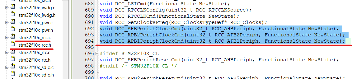
void RCC_AHBPeriphClockCmd(uint32_t RCC_AHBPeriph, FunctionalState NewState);
void RCC_APB2PeriphClockCmd(uint32_t RCC_APB2Periph, FunctionalState NewState);
void RCC_APB1PeriphClockCmd(uint32_t RCC_APB1Periph, FunctionalState NewState);/**
* @brief Enables or disables the AHB peripheral clock. AHB外设时钟使能或禁用。
* @param RCC_AHBPeriph: specifies the AHB peripheral to gates its clock.参数1:指定AHB外设对其时钟进行门控,也就是选择哪个外设
*
* For @b STM32_Connectivity_line_devices, this parameter can be any combination
* of the following values: STM32互联型设备,该参数可以是任何组合下列值中的一个
* @arg RCC_AHBPeriph_DMA1
* @arg RCC_AHBPeriph_DMA2
* @arg RCC_AHBPeriph_SRAM
* @arg RCC_AHBPeriph_FLITF
* @arg RCC_AHBPeriph_CRC
* @arg RCC_AHBPeriph_OTG_FS
* @arg RCC_AHBPeriph_ETH_MAC
* @arg RCC_AHBPeriph_ETH_MAC_Tx
* @arg RCC_AHBPeriph_ETH_MAC_Rx
*
* For @b other_STM32_devices, this parameter can be any combination of the
* following values:
STM32其他设备,该参数可以是任何组合下列值中的一个
* @arg RCC_AHBPeriph_DMA1
* @arg RCC_AHBPeriph_DMA2
* @arg RCC_AHBPeriph_SRAM
* @arg RCC_AHBPeriph_FLITF
* @arg RCC_AHBPeriph_CRC
* @arg RCC_AHBPeriph_FSMC
* @arg RCC_AHBPeriph_SDIO
*
* @note SRAM and FLITF clock can be disabled only during sleep mode.
* @param NewState: new state of the specified peripheral clock. 指定该被选中的状态ENABLE or DISABLE
* This parameter can be: ENABLE or DISABLE.
* @retval None
*/
void RCC_AHBPeriphClockCmd(uint32_t RCC_AHBPeriph, FunctionalState NewState)
{
/* Check the parameters */
assert_param(IS_RCC_AHB_PERIPH(RCC_AHBPeriph));
assert_param(IS_FUNCTIONAL_STATE(NewState));
if (NewState != DISABLE)
{
RCC->AHBENR |= RCC_AHBPeriph;
}
else
{
RCC->AHBENR &= ~RCC_AHBPeriph;
}
}与上面类似,只不过一个是APB2时钟控制,一个是APB1的,都是第一参数选择外设,第二个参数确定是使能还是失能
/**
  * @brief  Enables or disables the High Speed APB (APB2) peripheral clock.
  * @param  RCC_APB2Periph: specifies the APB2 peripheral to gates its clock.
  *   This parameter can be any combination of the following values:
  *     @arg RCC_APB2Periph_AFIO, RCC_APB2Periph_GPIOA, RCC_APB2Periph_GPIOB,
  *          RCC_APB2Periph_GPIOC, RCC_APB2Periph_GPIOD, RCC_APB2Periph_GPIOE,
  *          RCC_APB2Periph_GPIOF, RCC_APB2Periph_GPIOG, RCC_APB2Periph_ADC1,
  *          RCC_APB2Periph_ADC2, RCC_APB2Periph_TIM1, RCC_APB2Periph_SPI1,
  *          RCC_APB2Periph_TIM8, RCC_APB2Periph_USART1, RCC_APB2Periph_ADC3,
  *          RCC_APB2Periph_TIM15, RCC_APB2Periph_TIM16, RCC_APB2Periph_TIM17,
  *          RCC_APB2Periph_TIM9, RCC_APB2Periph_TIM10, RCC_APB2Periph_TIM11
  * @param  NewState: new state of the specified peripheral clock.
  *   This parameter can be: ENABLE or DISABLE.
  * @retval None
  */
void RCC_APB2PeriphClockCmd(uint32_t RCC_APB2Periph, FunctionalState NewState)
{
  /* Check the parameters */
  assert_param(IS_RCC_APB2_PERIPH(RCC_APB2Periph));
  assert_param(IS_FUNCTIONAL_STATE(NewState));
  if (NewState != DISABLE)
  {
    RCC->APB2ENR |= RCC_APB2Periph;
  }
  else
  {
    RCC->APB2ENR &= ~RCC_APB2Periph;
  }
}


/**
  * @brief  Enables or disables the Low Speed APB (APB1) peripheral clock.
  * @param  RCC_APB1Periph: specifies the APB1 peripheral to gates its clock.
  *   This parameter can be any combination of the following values:
  *     @arg RCC_APB1Periph_TIM2, RCC_APB1Periph_TIM3, RCC_APB1Periph_TIM4,
  *          RCC_APB1Periph_TIM5, RCC_APB1Periph_TIM6, RCC_APB1Periph_TIM7,
  *          RCC_APB1Periph_WWDG, RCC_APB1Periph_SPI2, RCC_APB1Periph_SPI3,
  *          RCC_APB1Periph_USART2, RCC_APB1Periph_USART3, RCC_APB1Periph_USART4,
  *          RCC_APB1Periph_USART5, RCC_APB1Periph_I2C1, RCC_APB1Periph_I2C2,
  *          RCC_APB1Periph_USB, RCC_APB1Periph_CAN1, RCC_APB1Periph_BKP,
  *          RCC_APB1Periph_PWR, RCC_APB1Periph_DAC, RCC_APB1Periph_CEC,
  *          RCC_APB1Periph_TIM12, RCC_APB1Periph_TIM13, RCC_APB1Periph_TIM14
  * @param  NewState: new state of the specified peripheral clock.
  *   This parameter can be: ENABLE or DISABLE.
  * @retval None
  */
void RCC_APB1PeriphClockCmd(uint32_t RCC_APB1Periph, FunctionalState NewState)
{
  /* Check the parameters */
  assert_param(IS_RCC_APB1_PERIPH(RCC_APB1Periph));
  assert_param(IS_FUNCTIONAL_STATE(NewState));
  if (NewState != DISABLE)
  {
    RCC->APB1ENR |= RCC_APB1Periph;
  }
  else
  {
    RCC->APB1ENR &= ~RCC_APB1Periph;
  }
}
GPIO库函数
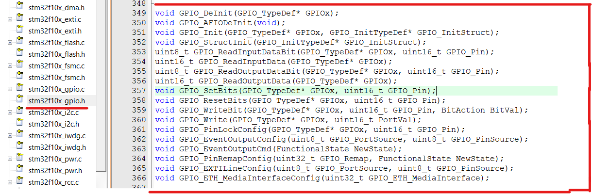
常用的几个
void GPIO_DeInit(GPIO_TypeDef* GPIOx);//使指定的GPIO外设会被复位
void GPIO_AFIODeInit(void);//复位AFIO外设
void GPIO_Init(GPIO_TypeDef* GPIOx, GPIO_InitTypeDef* GPIO_InitStruct);//重要,用结构体的参数来初始化GPIO口
void GPIO_StructInit(GPIO_InitTypeDef* GPIO_InitStruct);//把结构体变量赋一个默认值
//GPIO的读取函数
uint8_t GPIO_ReadInputDataBit(GPIO_TypeDef* GPIOx, uint16_t GPIO_Pin);
uint16_t GPIO_ReadInputData(GPIO_TypeDef* GPIOx);
uint8_t GPIO_ReadOutputDataBit(GPIO_TypeDef* GPIOx, uint16_t GPIO_Pin);
uint16_t GPIO_ReadOutputData(GPIO_TypeDef* GPIOx);

//GPIO_ReadOutputData()指读取指定的 GPIO端口输出 ,GPIO_ReadInputData()指读取指定的 GPIO端口输入。简单的说一个读取输出信号,一个读取输入信号,

//GPIO的写入函数
void GPIO_SetBits(GPIO_TypeDef* GPIOx, uint16_t GPIO_Pin);
void GPIO_ResetBits(GPIO_TypeDef* GPIOx, uint16_t GPIO_Pin);
void GPIO_WriteBit(GPIO_TypeDef* GPIOx, uint16_t GPIO_Pin, BitAction BitVal);
void GPIO_Write(GPIO_TypeDef* GPIOx, uint16_t PortVal);
GPIO输出
3-1LED闪烁
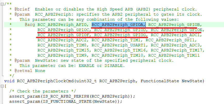
如不知道初始化选择AHB还是APB1或是APB2,可以去看他们的函数,看This parameter can be any combination of the following values:里面是否包含他们。
如本次要点亮的口是A0,那就是GPIOA,如下图可知他们都在APB2下,所以用RCC_APB2PeriphClockCmd(uint32_t RCC_APB2Periph, FunctionalState NewState)初始化即可。
用结构体初始化GPIO,第一个参数为GPIOX,这里为GPIOA.第二个就要先定义一个GPIO_InitTypeDef结构体了如:GPIO_InitTypeDef GPIO_InitStructure;
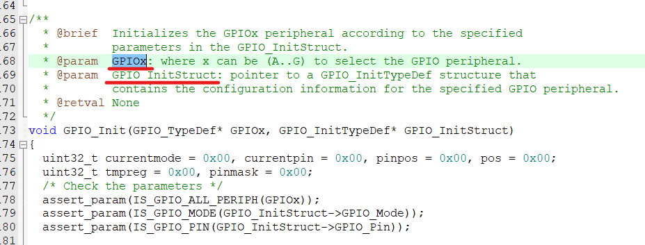
然后到GPIO_InitTypeDef定义看,结构体的变量含有,以及如何赋值:
分别是:
GPIO_Mode:
GPIO_Speed:
GPIO_Pin: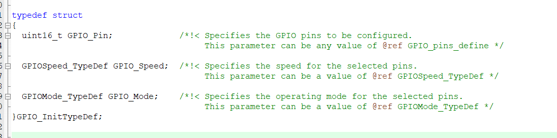
GPIO_Mode:选择模式:下面是8中工作模式,本次点灯用推挽输出所以选GPIO_Mode_Out_PP
typedef enum
{ GPIO_Mode_AIN = 0x0, //模拟输入
GPIO_Mode_IN_FLOATING = 0x04, //浮空输入
GPIO_Mode_IPD = 0x28, // 下拉输入
GPIO_Mode_IPU = 0x48, // 上拉输入
GPIO_Mode_Out_OD = 0x14, //开漏输出 (开漏模式,高电平没有驱动能力,低电平有驱动能力)
GPIO_Mode_Out_PP = 0x10, //推免输出 (推挽模式高、低电平都有驱动能力)
GPIO_Mode_AF_OD = 0x1C, //复用开漏
GPIO_Mode_AF_PP = 0x18 //复用推挽
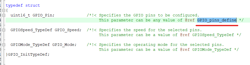
}GPIOMode_TypeDef;GPIO_Pin:选择member进行跳转:
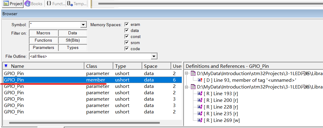
选中下面这个继续跳转:Cltr + F 寻找
本次用到的为0号引脚,所以用GPIO_Pin_0
#define GPIO_Pin_0                 ((uint16_t)0x0001)  /*!< Pin 0 selected */
#define GPIO_Pin_1                 ((uint16_t)0x0002)  /*!< Pin 1 selected */
#define GPIO_Pin_2                 ((uint16_t)0x0004)  /*!< Pin 2 selected */
#define GPIO_Pin_3                 ((uint16_t)0x0008)  /*!< Pin 3 selected */
#define GPIO_Pin_4                 ((uint16_t)0x0010)  /*!< Pin 4 selected */
#define GPIO_Pin_5                 ((uint16_t)0x0020)  /*!< Pin 5 selected */
#define GPIO_Pin_6                 ((uint16_t)0x0040)  /*!< Pin 6 selected */
#define GPIO_Pin_7                 ((uint16_t)0x0080)  /*!< Pin 7 selected */
#define GPIO_Pin_8                 ((uint16_t)0x0100)  /*!< Pin 8 selected */
#define GPIO_Pin_9                 ((uint16_t)0x0200)  /*!< Pin 9 selected */
#define GPIO_Pin_10                ((uint16_t)0x0400)  /*!< Pin 10 selected */
#define GPIO_Pin_11                ((uint16_t)0x0800)  /*!< Pin 11 selected */
#define GPIO_Pin_12                ((uint16_t)0x1000)  /*!< Pin 12 selected */
#define GPIO_Pin_13                ((uint16_t)0x2000)  /*!< Pin 13 selected */
#define GPIO_Pin_14                ((uint16_t)0x4000)  /*!< Pin 14 selected */
#define GPIO_Pin_15                ((uint16_t)0x8000)  /*!< Pin 15 selected */
#define GPIO_Pin_All ((uint16_t)0xFFFF) /*!< All pins selected */然后Speed:和上面类似:选择50MHZ就行GPIO_Speed_50MHz
typedef enum
{
  GPIO_Speed_10MHz = 1,
  GPIO_Speed_2MHz,
  GPIO_Speed_50MHz
}GPIOSpeed_TypeDef;注意GPIO_Init()第二个参数放结构体的地址加&符号
GPIO输出函数介绍
void GPIO_SetBits(GPIO_TypeDef* GPIOx, uint16_t GPIO_Pin);//把指定的GPIO函数置为高电平
void GPIO_ResetBits(GPIO_TypeDef* GPIOx, uint16_t GPIO_Pin);//把指定的GPIO函数置为低电平
void GPIO_WriteBit(GPIO_TypeDef* GPIOx, uint16_t GPIO_Pin, BitAction BitVal);//根据BitVal值来指定端口
void GPIO_Write(GPIO_TypeDef* GPIOx, uint16_t PortVal);//同时对GPIOx的16个参数进行写入操作
void GPIO_WriteBit(GPIO_TypeDef* GPIOx, uint16_t GPIO_Pin, BitAction BitVal);
函数,第三个值可以为Bit_RESET(低电平)或Bit_SET(高电平)
@param BitVal: specifies the value to be written to the selected bit.
* This parameter can be one of the BitAction enum values:
* @arg Bit_RESET: to clear the port pin
* @arg Bit_SET: to set the port pin
也可以这样代替:加一个强制类型转换就可以用0和1表示了
GPIO_WriteBit(GPIOA,GPIO_Pin_0,(BitAction)0);
GPIO_WriteBit(GPIOA,GPIO_Pin_0,(BitAction)1);LED闪烁代码:
#include "stm32f10x.h"                  // Device header
#include "Delay.h"
int main()
{
	RCC_APB2PeriphClockCmd(RCC_APB2Periph_GPIOA,ENABLE);//开启GPIOA的时钟

	GPIO_InitTypeDef GPIO_InitStructure;
	GPIO_InitStructure.GPIO_Mode = GPIO_Mode_Out_OD;
	GPIO_InitStructure.GPIO_Speed = GPIO_Speed_50MHz;
	GPIO_InitStructure.GPIO_Pin = GPIO_Pin_0;
	GPIO_Init(GPIOA, &GPIO_InitStructure);//GPIOA0推挽输出50MHZ
//	GPIO_ResetBits(GPIOA,GPIO_Pin_0);
//	GPIO_SetBits(GPIOA,GPIO_Pin_0);
	while(1)
	{
		GPIO_WriteBit(GPIOA,GPIO_Pin_0,Bit_RESET);
		Delay_ms(500);
		GPIO_WriteBit(GPIOA,GPIO_Pin_0,Bit_SET);
		Delay_ms(500);

		GPIO_WriteBit(GPIOA,GPIO_Pin_0,(BitAction)0);
		Delay_ms(500);
		GPIO_WriteBit(GPIOA,GPIO_Pin_0,(BitAction)1);
		Delay_ms(500);
	}
}
3-2LED流水灯
通过结构体一下初始化多个端口,通过安按位或的方式进行多个初始化,时钟控制也可以通过按位或选择多个外设
GPIO_InitStructure.GPIO_Pin = GPIO_Pin_0 | GPIO_Pin_1 | GPIO_Pin_2 | GPIO_Pin_3 | GPIO_Pin_4 | GPIO_Pin_5 | GPIO_Pin_6 | GPIO_Pin_7;RCC_APB2PeriphClockCmd(RCC_APB2Periph_GPIOA|RCC_APB2Periph_GPIOA,ENABLE);原因:原因都类似
#define GPIO_Pin_0                 ((uint16_t)0x0001)  /*!< Pin 0 selected */
#define GPIO_Pin_1                 ((uint16_t)0x0002)  /*!< Pin 1 selected */
#define GPIO_Pin_2                 ((uint16_t)0x0004)  /*!< Pin 2 selected */
#define GPIO_Pin_3                 ((uint16_t)0x0008)  /*!< Pin 3 selected */
#define GPIO_Pin_4                 ((uint16_t)0x0010)  /*!< Pin 4 selected */
#define GPIO_Pin_5                 ((uint16_t)0x0020)  /*!< Pin 5 selected */
#define GPIO_Pin_6                 ((uint16_t)0x0040)  /*!< Pin 6 selected */
#define GPIO_Pin_7                 ((uint16_t)0x0080)  /*!< Pin 7 selected */
#define GPIO_Pin_8                 ((uint16_t)0x0100)  /*!< Pin 8 selected */
#define GPIO_Pin_9                 ((uint16_t)0x0200)  /*!< Pin 9 selected */
#define GPIO_Pin_10                ((uint16_t)0x0400)  /*!< Pin 10 selected */
#define GPIO_Pin_11                ((uint16_t)0x0800)  /*!< Pin 11 selected */
#define GPIO_Pin_12                ((uint16_t)0x1000)  /*!< Pin 12 selected */
#define GPIO_Pin_13                ((uint16_t)0x2000)  /*!< Pin 13 selected */
#define GPIO_Pin_14                ((uint16_t)0x4000)  /*!< Pin 14 selected */
#define GPIO_Pin_15                ((uint16_t)0x8000)  /*!< Pin 15 selected */
#define GPIO_Pin_All               ((uint16_t)0xFFFF)  /*!< All pins selected */
由上可以看出每个占其中一位为1,所以可以通过按位或进行操作,也可以通过GPIO_Pin_All把16个口全部赋值代码:注意A13、PB3、PB4这几端口是调试端口如当普通端口使用要额外配置
#include "stm32f10x.h"                  // Device header
#include "Delay.h"
int main()
{
	RCC_APB2PeriphClockCmd(RCC_APB2Periph_GPIOA,ENABLE);//开启GPIOA的时钟

	GPIO_InitTypeDef GPIO_InitStructure;
	GPIO_InitStructure.GPIO_Mode = GPIO_Mode_Out_OD;
	GPIO_InitStructure.GPIO_Speed = GPIO_Speed_50MHz;
//	GPIO_InitStructure.GPIO_Pin = GPIO_Pin_0 | GPIO_Pin_1 | GPIO_Pin_2 | GPIO_Pin_3 | GPIO_Pin_4 | GPIO_Pin_5 | GPIO_Pin_6 | GPIO_Pin_7;
	GPIO_InitStructure.GPIO_Pin = GPIO_Pin_All;
	GPIO_Init(GPIOA, &GPIO_InitStructure);//GPIOA0推挽输出50MHZ
	while(1)
	{
		GPIO_Write(GPIOA,~0x0001);//0000 0000 0000 0001
		Delay_ms(500);
		GPIO_Write(GPIOA,~0x0002);//0000 0000 0000 0010
		Delay_ms(500);
		GPIO_Write(GPIOA,~0x0004);//0000 0000 0000 0100
		Delay_ms(500);
		GPIO_Write(GPIOA,~0x0008);//0000 0000 0000 1000
		Delay_ms(500);
		GPIO_Write(GPIOA,~0x0010);//0000 0000 0001 0000
		Delay_ms(500);
		GPIO_Write(GPIOA,~0x0020);//0000 0000 0010 0000
		Delay_ms(500);
		GPIO_Write(GPIOA,~0x0040);//0000 0000 0100 0000
		Delay_ms(500);
		GPIO_Write(GPIOA,~0x0080);//0000 0000 1000 0000
		Delay_ms(500);

	}
}
3-3蜂鸣器
#include "stm32f10x.h"                  // Device header
#include "Delay.h"
int main()
{
	RCC_APB2PeriphClockCmd(RCC_APB2Periph_GPIOB,ENABLE);//开启GPIOA的时钟
	GPIO_InitTypeDef GPIO_InitStructure;
	GPIO_InitStructure.GPIO_Mode = GPIO_Mode_Out_OD;
	GPIO_InitStructure.GPIO_Speed = GPIO_Speed_50MHz;
	GPIO_InitStructure.GPIO_Pin = GPIO_Pin_12;
	GPIO_Init(GPIOB, &GPIO_InitStructure);//GPIOA0推挽输出50MHZ
	while(1)
	{
		GPIO_ResetBits(GPIOB,GPIO_Pin_12);
		Delay_ms(100);
		GPIO_SetBits(GPIOB,GPIO_Pin_12);
		Delay_ms(100);
		GPIO_ResetBits(GPIOB,GPIO_Pin_12);
		Delay_ms(100);
		GPIO_SetBits(GPIOB,GPIO_Pin_12);
		Delay_ms(700);
	}
}
GPIO输入
传感器模块
如光敏、热敏、红外(对射和反射)
一般是A0输出模拟信号,D0输出数字信号,一般是越强阻值越小
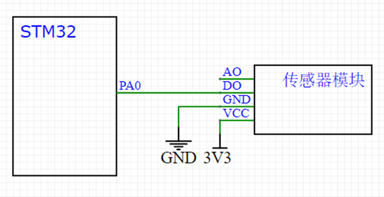
按键接线
建议1或2,经常用:
1、这种接法必须要求PA0是上拉模式,也就是默认带高电平,这样才能保证按下为低电平,不按为高电平。否者引脚悬空,无法确认高低电平。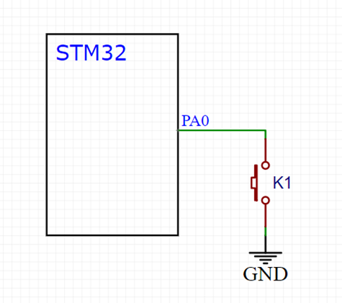
2、这种已经带一个上拉了,配置浮空输入和上拉输入都可以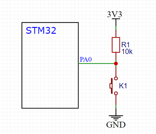
3、配置为下拉输入,实现按下时引脚为高电平,松手时为默认低电平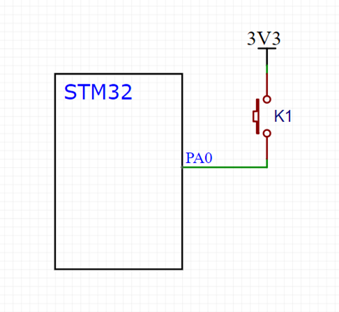
4、PA0下拉输入或者浮空输入模式。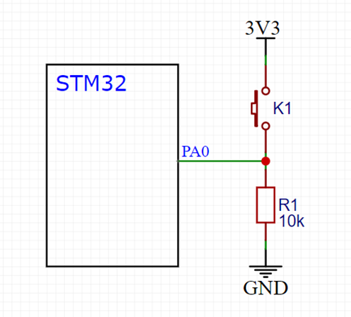
3-4按键控制LED
不操作默认低电平
//GPIO的读取函数
uint8_t GPIO_ReadInputDataBit(GPIO_TypeDef* GPIOx, uint16_t GPIO_Pin);//读取输入数据寄存器某一端口的数值
uint16_t GPIO_ReadInputData(GPIO_TypeDef* GPIOx);//读取整个输入数据寄存器的数值
uint8_t GPIO_ReadOutputDataBit(GPIO_TypeDef* GPIOx, uint16_t GPIO_Pin);//读取输出数据寄存器某一端口的数值
uint16_t GPIO_ReadOutputData(GPIO_TypeDef* GPIOx);//读取整个输出数据寄存器的数值